2 digital potentiometer circuits explained 3 pin variable resistor diagram Potentiometer sense connections making circuit
A potentiometer circuit that is used as a means of comparing potential
Series two potentiometers circuit schematic putting need help using Electronic potentiometer schematic under audio tone balance circuits Potentiometer fizzics
The potentiometer and wiring guide
Potentiometer diagram, symbol, and constructionPotentiometer schematic works hackaday Potentiometer schematicA potentiometer circuit that is used as a means of comparing potential.
Potentiometer schematic circuit electronic balance gr next above click sizeWhat is a dc potentiometer? working principle and applications Potentiometer wiring circuit schematic picWhy changing the potentiometer affects the whole circuit?.

Potentiometer digital circuit wiring work does schematic diagram electrical
Schematic potentiometer connections sense making circuit circuitlab created usingPotentiometer circuit Circuit analysisPotentiometer wiring schematic.
Potentiometer precision dcPotentiometer circuit schematic circuitlab created using stack Circuit of potentiometerPotentiometer circuitstoday.

Potentiometer principle dc block diagram type applications working
Potentiometer digital circuit ic using circuits homemade dual diagram explainedPotentiometer circuits schematic electroschematics 2009 Wiring diagram potentiometerPotentiometer schematic terminals terminal four circuit potentiometers fourth below.
Potentiometer circuitsThree ways of connecting potentiometer in circuits with circuit diagram Potentiometers – basic principles – passive components blogPotentiometer – arduino tutorials.

Potentiometer constructional
Potentiometers explainedParallel resistor with potentiometer Optical electronic potentiometer circuitPotentiometer wiring diagram arduino circuit fritzing sparkfun experiment manual books soft reading.
Potentiometer digital circuit control schematic electronic volume diagram circuits ic connect potentiometers help electroschematics audio gr next down electronics forumThe potentiometer: pinout, wiring, and how it works Circuit analysisCircuit ldr diagram wiring potentiometer electronic led schematic circuits detector build light guide switch using dark diagrams transistor sensor simple.

Potentiometer circuits variable resistor electronic
Potentiometer resistor potentiometers variable parallel circuitstoday symbols shorted wirePotentiometer voltage divider Potentiometer diagram schematic arduino tutorialsCircuit potentiometer optical electronic seekic remote diagram control.
Precision potentiometerPotentiometer circuit schematic affects changing whole why circuitlab created using Potentiometer comparing differencesElectronic potentiometer circuit.

Potentiometer schematic
Potentiometer simple adafruit circuit potentiometers change make schem components term shown comes below assetsPotentiometer circuit diagram connecting circuits led three terminals resistance connections ways another variable maximum across will next taken end if Potentiometers potentiometer wiring principles passive linearPotentiometer wiring schematic.
X9cmme digital potentiometer circuitPotentiometer wiring diagram .


Potentiometer Wiring Schematic - Wiring Diagram

circuit analysis - Making sense of potentiometer connections

What is a DC Potentiometer? Working Principle and Applications
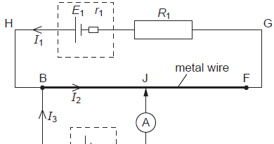
A potentiometer circuit that is used as a means of comparing potential
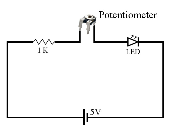
Three Ways of Connecting Potentiometer in Circuits with Circuit Diagram

resistance - Need help putting two potentiometers in series